
🌌 Real-Time GPU Raytracing Engine
sponza.mp4
RT is a GPU‑accelerated raytracing engine built as a school project to explore real‑time rendering techniques using OpenGL and compute shaders. By dispatching a full‑screen triangle and leveraging GLSL compute shaders, RT shoots rays per pixel directly on the GPU, enabling interactive exploration of advanced lighting, materials, and even non‑Euclidean geometries.
🚀 Purpose:
- Demonstrate end‑to‑end GPU ray generation and shading
- Experiment with custom denoising and video output pipelines
- Provide a modular framework for adding new primitives, materials, and effects
- Full‑screen Triangle Dispatch: For efficient compute shader ray launches
- Custom Ray Generation: From camera parameters (FOV, aspect ratio, lens)
- Material System: With diffuse, reflective, glossy, transparent & emissive materials
- Volumetric Lighting: Fully customizable volumetric fog
- Non‑Euclidean Portals: Seamless teleportation of linked portals for non euclidian geomtry
- High‑Performance Traversal: SAH‑BVH for scenes with tens of millions of triangles
- Custom Denoising: Wavelet A-trous algorithm modified
- FFmpeg‑based Path Renderer: Exporting video from user-made path throught the scene
- Mass clusterizing: Allowing parallelizing on multiple GPU over the network
| Component | Description |
|---|---|
| OpenGL | Context creation, buffer management |
| GLSL Compute Shader | Ray generation, acceleration structure traversal |
| C++20 | Core engine logic and data structures |
| FFmpeg | Path‑through networked video renderer |

Real‑time raytraced Sponza interior with global illumination.

Portal‑based non‑Euclidean scene demonstration.
-
Window & Context
-
Created via GLFW with a core‑profile OpenGL 4.3 context.
-
Connected to ImGUI.
-
-
Buffer & Texture Allocation
-
Full‑Screen Triangle: A single VAO/VBO with 3 vertices covering NDC space:
// Vertex positions in NDC: (−1,−1), (3,−1), (−1,3)
const vec2 triVerts[3] = vec2[3](vec2(-1), vec2(3, -1), vec2(-1, 3));
-
Image2D Textures: Created with
glTexImage2D(RGBA32F) for:-
output_texture (final color)
-
output_accum_texture (color accumulation)
-
normal, position, light, light_accum, color buffers
-
-
Bound each to a unique image unit (0–7) for compute shader writes.
-
-
Shader Compilation & Dispatch
-
Compile
shaders/compute.glslas a compute shader. -
Query workgroup size (16×16) and compute dispatch dimensions as:
GLuint groupsX = (width  + localSizeX - 1) / localSizeX;
GLuint groupsY = (height + localSizeY - 1) / localSizeY;
glDispatchCompute(groupsX, groupsY, 1);
glMemoryBarrier(GL_SHADER_IMAGE_ACCESS_BARRIER_BIT);
-
Swap & present the resulting texture each frame.
-
🔗 View full compute shader source
// Initialize a camera ray with depth‑of‑field and jitter for free anti-aliasing
Ray initRay(vec2 uv, inout uint rng_state) {
    // Convert FOV to focal length
    float focal_length = 1.0 / tan(radians(camera.fov) * 0.5);

    // Ray in view‑space
    vec3 view_ray = normalize(vec3(uv.x, uv.y, -focal_length));
    // Transform to world space
    vec3 dir = normalize((inverse(camera.view_matrix) * vec4(view_ray, 0.0)).xyz);
    vec3 orig = camera.position;

    // Depth‑of‑field: sample lens disk
    vec3 right = camera.view_matrix[0].xyz;
    vec3 up    = camera.view_matrix[1].xyz;
    vec3 focal_pt = orig + dir * camera.focus_distance;
    float r = sqrt(randomValue(rng_state));
    float θ = 2.0 * M_PI * randomValue(rng_state);
    vec2 lens = camera.aperture_size * r * vec2(cos(θ), sin(θ));
    orig += right * lens.x + up * lens.y;
    dir   = normalize(focal_pt - orig);

    return Ray(orig, dir, 1.0 / dir);
}

void main() {
    ivec2 pix = ivec2(gl_GlobalInvocationID.xy);

	...

    // Initialize RNG per‑pixel & jitter UV
    uint rng = uint(u_resolution.x) * pix.y + pix.x + u_frameCount * 719393;
    vec2 jitter = randomPointInCircle(rng);
    vec2 uv = ((vec2(pix) + jitter) / u_resolution) * 2.0 - 1.0;
    uv.x *= u_resolution.x / u_resolution.y;

	...
}Our RT comes with a variety of built‑in geometric primitives, each traced mathematically in the compute shader:
| Primitive | Description & Notes |
|---|---|
| Cube | Axis‑aligned cube. |
| Cylinder | Finite cylinder with end caps; parameterized by radius, height and rotation. |
| Plane | Infinite plane defined by a point & normal. |
| Portal | Any paired "windows" implementing non‑Euclidean teleportation. See "Advanced Features" below. |
| Quad | Rectangular object useful for billboards or area lights. |
| Sphere | Round object useful for sphere light. |
| SpotLight | Directional point with cone angle, used for volumetric scattering. |
| Triangle | Single triangle, primitive building block for custom meshes and SAH‑BVH traversal. |
📌 Each primitive stores its own transform (position, rotation, scale) and material index; the compute shader branches on
obj.typefor intersection tests.
Materials in RT are defined by a compact struct in C++ and mirrored in GLSL for shading:
typedef struct s_Material {
    glm::vec3 color;               // Base albedo
    float     emission;            // Emissive strength
    float     roughness;           // [1=mirror … 0=diffuse]
    float     metallic;            // [probability of reflecting]
    float     refraction;          // IOR for transmissive materials
    int       type;                // 0=Lambert,1=Dielectric,2=Transparent,3=Checker...
    int       texture_index;       // Albedo texture lookup
    int       emission_texture_index; // Emissive texture lookup
} Material;-
Lambert: Diffuse, energy‑conserving scattering.
-
Dielectric: Glass‑like refraction & Fresnel.
-
Transparent: Fully transparent with or without absorption.
-
Semi‑Transparent/Glossy: Blends refraction & reflection based on roughness.
-
Metallic: Perfect conductor with roughness–controlled gloss.
-
Checker Pattern: Procedural UV checker.
-
Textured: Any 2D texture bound to texture_index.
-
Emissive: Uses emission_texture_index or uniform emission color for light sources.
💡 Roughness & metallic parameters feed a microfacet BRDF in the shader; textures are sampled via sampler2D arrays.
-
Loads .obj geometry with arbitrary face sizes.
-
Triangulates N‑gons on the fly for BVH insertion.
-
Parses .mtl files, matches material names to our Material struct, and uploads textures.
🔧 Custom models, from simple props to complex. Automatically inheriting transforms and materials.
🔗 View OBJ parser implementation
Our RT uses stb_image to load 2D images (albedo & emissive maps) on the CPU, then uploads them as GLSL sampler2D arrays. In the compute shader:
-
Binded albedo maps at
mat.texture_index, emissive maps atmat.emissive_texture_index. -
Sample with UVs interpolated per‑hit:
  if (mat.texture_index != -1)
      color *= texture(textures[mat.texture_index], uv).rgb;
  if (mat.emission_texture_index != -1)
  {
      vec3 emission = mat.emission * texture(emissive_textures[mat.emission_texture_index], uv).rgb;

      light += mat.emission * emission;
  }
  else
  {
      vec3 mat_color = (mat.type == 3) ? getCheckerboardColor(mat, hit) : mat.color;

      color *= mat_color;
      light += mat.emission * mat_color;
  }
Portals link two planes in space, allowing rays (and the camera) to teleport seamlessly.
Ray portalRay(Ray ray, hitInfo hit)
{
    GPUObject p1 = objects[hit.obj_index];
    GPUObject p2 = objects[int(p1.radius)]; // paired portal index is stored in radius

    // Compute local hit offset
    vec3 rel = hit.position - p1.position;

    // Rotation to align portal normals
    mat3 R = mat3(p2.rotation) * transpose(mat3(p1.rotation));

    // If portals face roughly the same way, apply reflection to flip
    if (dot(p1.normal, p2.normal) > 0.0) {
        mat3 refl = mat3(1.0) - 2.0 * outerProduct(p1.normal, p2.normal);
        R *= refl;
    }

    // Teleport ray origin & direction
    ray.origin    = p2.position + R * rel;
    ray.direction = normalize(R * ray.direction);

    // Avoid self‑intersection
    ray.origin += ray.direction * 0.01;

    return ray;
}-
Read portal A (
p1) and its target B (p2). -
Compute the local offset of the hit point (
rel). -
Build rotation matrix
Rto transform from A’s space to B’s space. -
If normals point the same way, apply a mirror flip so the ray emerges correctly.
-
Offset the new origin slightly along the new direction to prevent re‑hitting the portal.
int Camera::portalTeleport(Scene* scene, float dt, Renderer& renderer)
{
    static int cooldown = 10;
    if (cooldown-- > 0) return 0;

    // Find nearest portal intersection in front of camera
    float best_dist = FLT_MAX;
    GPUObject found;
    for (auto& obj : scene->getObjectData()) {
        if (obj.type != (int)Object::Type::PORTAL) continue;
        // Project camera pos onto portal plane, check inside quad
        // … alphaBeta test …
        if (/* inside and approaching */) {
            float d = /* distance to plane */;
            if (d < best_dist) { best_dist = d; found = obj; }
        }
    }
    if (best_dist == FLT_MAX) return 0;  // no portal hit

    // Reset cooldown
    cooldown = 10;
    auto linked = scene->getObjectData()[found.radius];

    // Compute transform between portals (with optional reflection)
    mat3 X = mat3(linked.transform) * inverse(mat3(found.transform));
    if (dot(found.normal, linked.normal) > 0)
        X *= (mat3(1.0f) - 2.0f * outerProduct(linked.normal, linked.normal));

    // Teleport position & carry on remaining movement
    vec3 relPos = position - found.position;
    vec3 newRel = X * relPos;
    float moved = length(velocity * dt) - best_dist + 0.1f;
    vec3 carry = moved * (X * linked.normal);
    position = linked.position + newRel - carry;

    // Rotate camera basis vectors & velocity
    forward = X * forward; up = X * up; right = X * right;
    velocity = X * velocity;
    updateCameraDirections();
}-
Complete seamless teleportation
-
Projects camera onto portal plane, checks if within quad bounds.
-
Computes a 3×3 transform (and mirror if needed) to carry position & orientation.
-
Applies any leftover movement to exit the linked portal naturally.
Emissive materials in our RT are treated as Monte Carlo light sources. When a pathtrace ray samples a surface with material.emission > 0, it simply adds that emission term and terminates. This is implemented by:
if (mat.emission > 0.0)
{
    // Add emitted radiance and end the path
    radiance += throughput * mat.emission * mat.color;
    break ; // Stop bouncing
}
This straightforward approach lets you place glowing objects or emissive textures anywhere in the scene (e.g. neon signs, light panels, or emissive 3D models).

A simple emissive sphere "lightbulb" illuminating its surroundings.
For more cinematic effects like light shafts through fog, we simulate volumetric scattering using a simplified participating medium (e.g. air with some dust or mist).
We based our implementation on Noah Pitts' excellent writeup and followed the general idea of phase scattering along the camera ray.

Visual explanation from Noah Pitts
-
Randomly sample a distance
talong the ray. -
If the sample is inside a foggy volume and before hitting any object, we:
-
Compute transmittance (light absorption).
-
Compute phase scattering using the Henyey-Greenstein phase function.
-
Add light contribution from a spotlight only (custom behavior).
-
Spawn a new ray from the scatter point with a sampled new direction.
-
-
This happens probabilistically per ray, and when it does, we accumulate soft beams of light from the spotlight into the final pixel.
We diverged from the original article in a few important ways:
-
Only a specific spotlight is allowed to contribute to the volumetric lighting.
-
This makes fog behavior customizable per light, letting us mix color, falloff, and beam shape for creative control.
-
Fog is not just gray, its hue and density vary depending on the light it scatters.
🔦 This lets us create atmospheric shafts, volumetric cones, and sci-fi effects that are tightly bound to how we configure the spotlight.
To evaluate the realism of our lighting pipeline, we recreated the environment shown in this Reddit video:
🔗 SipsTea Scene
Our raytracer reproduced similar illumination, especially in terms of:
-
Emissive bounce light from screens and panels.
-
Soft fog and god rays from spotlights through dusty air.


✅ This validates that our lighting (emissive + volumetric) behaves physically close to reality.
Real-time path tracing requires major optimization work, especially when targeting scenes with millions of triangles and noisy outputs. Here’s how we tackled it:
To make ray-triangle intersections faster, we implemented a Bounding Volume Hierarchy (BVH) using the Surface Area Heuristic (SAH) — following Jacco Bikker’s excellent writeup.
SAH BVH partitioning from Jacco Bikker’s article
-
Each node in the BVH holds a bounding box (
AABB) around a subset of triangles. -
When subdividing, we test different split planes along the X, Y, and Z axes.
-
For each candidate, we compute the SAH cost:
Cost = Ctrav + (AL / AP) × NL × Cisect + (AR / AP) × NR × Cisect
Where:
-
AL, AR, AP: Surface areas of left, right, and parent bounding boxes
-
NL, NR: Triangle counts in each child
-
Ctrav, Cisect: Empirically chosen traversal and intersection costs
-
This cost function encourages spatial splits that reduce overlap and keep bounding boxes tight.
for (int axis = 0; axis < 3; axis++)
{
    for (int i = 0; i < num_test_per_axis; i++)
    {
        float candidate_pos = ...;
        float cost = evaluateSah(triangles, axis, candidate_pos);

        if (cost < best_cost)
        {
            best_axis = axis;
            best_pos = candidate_pos;
            best_cost = cost;
        }
    }
}-
After the best split is chosen, triangles are partitioned based on centroid position.
-
Recursion continues until leaf conditions are met (e.g.
<= 4triangles).
Once built, the recursive BVH structure is flattened into a linear array for efficient traversal on the GPU. Each node holds:
-
AABB bounds
-
Child indices or triangle offsets
-
Flags to determine whether it's a leaf or inner node
This enables fast, stack-based traversal directly in GLSL.

SAH BVH partitioning debug view from our RT
Thanks to this optimization, the renderer supports multi-million triangle meshes efficiently.

Render of heavy-scene with multi-million triangles
Scene complexity is no longer the bottleneck — GPU ray traversal performance scales well thanks to the flattened BVH.
For denoising, we used the A-Trous Wavelet Filter technique described in this great 2010 paper by Joost van Dongen.

A-Trous filter denoising from Joost van Dongen’s paper
The filter applies iterative blurring with edge-aware weights, controlled by color and normal similarity. Each iteration doubles the sampling step (à trous = “with holes”). This removes high-frequency noise while preserving edges and structure.
⚙️ Custom Modifications Unlike traditional implementations, we modified the filter to run only on the light output texture, not on the full pixel buffer.
🖼️ This preserves detail in texture-mapped objects, while still removing lighting noise from the path tracer.

Before Denoising

After Denoising
You’ll see a huge difference in indirect light quality: soft shadows, emissive bounce, and foggy light rays become clear in just a few samples.
To create camera animations and cinematic renders, we developed a custom path-following renderer built on top of the FFmpeg C API. The idea is simple but powerful:
-
You define a path by either manually moving the camera or using preset keyframes.
-
The tool then smooths this path (using Bézier and spline interpolation) to produce a cinematic sequence.
-
For each point along this path, the renderer produces a high-quality frame using the path tracer.
-
All frames are automatically encoded into a video using FFmpeg (you can choose any encoder available), fully customizable FPS and samples per frame.
-
Number of samples per frame
-
Choice of using denoising
-
Camera speed and orientation smoothing
To handle heavy rendering tasks, we implemented a distributed rendering system that supports multi-GPU.
All rendering clients connect to a central server using local sockets. Each client takes a set of frames and processes them independently with full GPU acceleration.
This can result in a massive performance increase, sometimes hundreds to thousands of times faster than local rendering, depending on the number of machines and GPUs used.
Each client runs the same OpenGL path tracer, but only on assigned frame chunks. The server:
-
Splits the frame list across clients
-
Tracks progress of each job
-
Merges the frames into a single image stream
-
Hands them to FFmpeg in real-time
The renderer includes a built-in ImGui interface that:
-
Displays the camera path on the UI
-
Lets you preview the render path
-
Shows real-time progress of each network client

Screenshot of the ImGui interface with client frame stats and camera spline

Demo video of a rendered animation path
...
...
...
Launching the program is straightforward. The binary accepts a few optional arguments when run:
./RT.exe [options] <scene name> [options]-
Provide a render path file via -r or --renderpath to render a pre-defined animation
-
Use the -h or --headless flag to start rendering immediately and close automatically once done. Useful for scripting or server jobs
This makes it easy to automate animations or batch rendering workflows on render farms or across networked clients.
Once launched (in GUI mode), the renderer exposes a rich set of runtime settings through an intuitive ImGui interface:
-
Accumulate toggle for progressive refinement
-
Bounce count for controlling ray recursion depth
-
FOV, Aperture, and Focus distance controls
-
Perfect for testing depth-of-field effects or scene convergence live
-
Color and Emission sliders
-
Type selection: Lambertian, Refractive, Transparent, Checker
-
Parameters change contextually based on type (e.g., roughness/metallic for PBR, refraction index for glass)
-
Real-time updates with immediate visual feedback
-
Toggle fog globally with one checkbox
-
Adjust absorption, scattering, and phase function (g) for participating media
-
Internally updates shader macros and reloads code seamlessly
-
Enable/disable denoiser
-
Select number of passes (even values for the custom wavelet filters)
-
Tune color, position, and normal sensitivity values (c_phi, p_phi, n_phi)
-
Extremely useful for improving image quality at lower sample counts
-
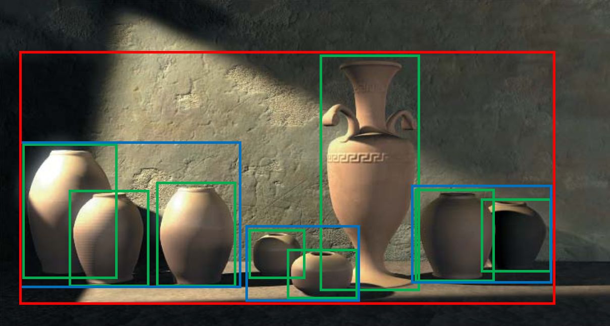
Activate debug mode to visualize BVH traversal and scene diagnostics
-
Adjust debug modes, box thresholds, and triangle thresholds
-
Great for analyzing scene structure or debugging performance issues
-
Display of current FPS, frame count, and number of objects in the scene
-
Toggle output texture index to switch between different render targets (e.g., normal, albedo, denoise)
All changes trigger re-renders when needed, and accumulation resets when essential parameters are modified, ensuring that visuals always reflect the most recent settings.
...
...
This project is licensed under the MIT License - see the LICENSE file for details.
Developed by Contré Yavin and Tom Moron as part of RT at 42 School.
- My GitHub: @TheRedShip
- Tom's GitHub: @arandompig
⭐ Star this repository if you liked it! ⭐